Spin spirals
Generalized Bloch condition
Spin spirals may be conveniently modeled using a generalization of the Bloch condition (set LNONCOLLINEAR=.TRUE. and LSPIRAL=.TRUE.):
i.e., from one unit cell to the next the up- and down-spinors pick up an additional phase factor of and , respectively, where R is a lattice vector of the crystalline lattice, and q is the so-called spin-spiral propagation vector.
The spin-spiral propagation vector is commonly chosen to lie within the first Brillouin zone of the reciprocal space lattice, and has to be specified by means of the QSPIRAL-tag.
The generalized Bloch condition above gives rise to the following behavior of the magnetization density:
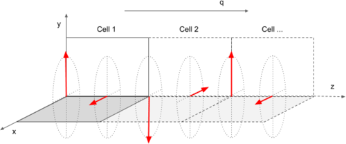
This is schematically depicted below: the components of the magnization in the xy-plane rotate about the spin-spiral propagation vector q.
N.B.: This does not mean that the magnetisation density may not have contributions along the z-direction.
These, however, will not be affected by the generalized Bloch condition, i.e., will simply show the usual cell periodicity.
If one explicitly wants to keep the magnetisation density from developing components along the z-direction set:
LZEROZ = .TRUE.
This will set at each iteration step of the electronic minimisation.
Basis set considerations
The generalized Bloch condition redefines the Bloch functions as follows:
This changes the Hamiltonian only minimally:
where in and the kinetic energy of a plane wave component changes to:
In the case of spin-spiral calculations the energy cutoff of the basis set of the individual spinor components is specified by means of the ENINI-tag.
Additionally one needs to set ENMAX appropriately: ENMAX needs to be chosen larger than ENINI, and large enough so that the plane wave components of both the up-spinors as well as the components of the down-spinor all have a kinetic energy smaller than ENMAX. This is the case when:
where
In most cases it is more than sufficient to set ENMAX=ENINI+100.
To judge whether ENMAX was chosen large enough one will always get a warning at runtime, e.g.
 -----------------------------------------------------------------------------
|                                                                             |
|           W    W    AA    RRRRR   N    N  II  N    N   GGGG   !!!           |
|           W    W   A  A   R    R  NN   N  II  NN   N  G    G  !!!           |
|           W    W  A    A  R    R  N N  N  II  N N  N  G       !!!           |
|           W WW W  AAAAAA  RRRRR   N  N N  II  N  N N  G  GGG   !            |
|           WW  WW  A    A  R   R   N   NN  II  N   NN  G    G                |
|           W    W  A    A  R    R  N    N  II  N    N   GGGG   !!!           |
|                                                                             |
|      To represent the spin spiral you requested, with a kinetic             |
|      energy cutoff of ENINI=  300.00 eV, choose ENMAX >  331.21 eV          |
|      Currently ENMAX=  400.00 eV                                            |
|                                                                             |
 -----------------------------------------------------------------------------
Symmetry
Generally the introduction of a spin-spiral will lower the symmetry of the system. At present VASP can not correctly account for the presence of a spin-spiral in its symmetry analysis.
Therefore the use of symmetry has to be switched of completely:
ISYM = -1
Initialization of the magnetic subsystem
As for all calculations on magnetic systems it is highly advisable to initialise the magnetic subsystem by means of the MAGMOM tag.
Note that, in case one does not specify initial magnetic moments, the initial order of the magnetic subsystem will be ferromagnetic (see the MAGMOM default values), and even if the groundstate of your system is not ferromagnetic, the initial ferromagnetic state might very well be a local minimum in which the system can remain stuck during the electronic minimisation.
Of course, in case of spin-spiral calculations the magnetic subsystem is not completely characterized by the magnetic configuration within the unit cell, but will additionally depend on how the magnetization density changes from one unit cell to the next as determined by the spiral propagation vector.
Consider the following two examples:
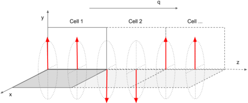
- Two magnetic atoms per unit cell, both with initial magnetic moments M along the y-axis and :
MAGMOM = 0 M 0  0 M 0
QSPIRAL= 0.0 0.0 0.5
- i.e., a double layer antiferromagnet:
- Two magnetic atoms per unit cell, both with initial magnetic moments M along the y- and x-axis, respectively, and :
MAGMOM = 0 M 0  M 0 0
QSPIRAL= 0.0 0.0 0.5
- i.e., a spin spiral:
N.B.: both of the aforementioned magnetic arrangements obey the same generalized Bloch condition, , and during the electronic minimisation one may transform into the other if that lowers the total energy.
In other words the generalized Bloch condition dictates the change in the magnetization density from one unit cell to the next, but it does not explicitly constrain the magnetic order within the unit cells themselves.
Local magnetic moments
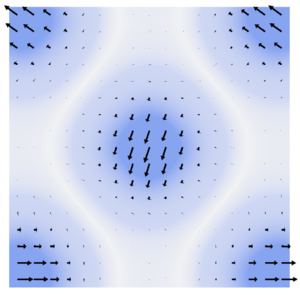
Analysing the magnetisation density from spin-spiral calculations in terms of site resolved local magnetic moments is a bit more involved than usual. Problems arise from the fact that in most cases the spin-spiral period will not be commensurate with the unit cell (otherwise there would be no reason to use the generalised Bloch theorem). This means that implicitly the magnetisation density is not cell periodic, as illustrated in the figure below:
The usual ways to analyse the site resolved local charge density and magnetisation (e.g. setting the LORBIT-tag: output in the PROCAR file and at the end of the OUTCAR file) do not account for this. As a workaround one may (ab)use the infrastructure created for the constrained magnetic moment approach, as follows:
I_CONSTRAINED_M = 1
LAMBDA = 0.0
i.e., one switches on the constrained magnetic moment approach (I_CONSTRAINED_M=1) but sets the penalty potential to zero (LAMBDA=0.0).
N.B.: do not forget to set RWIGS appropriately.
The magnetisation density will correctly integrated inside site centered sphere of radius RWIGS, and the resulting local magnetic moments are written under M_int, to the OSZICAR file. For instance:
 E_p =  0.00000E+00  lambda =  0.000E+00
<lVp>=  0.00000E+00
 DBL =  0.00000E+00
 ion        MW_int                 M_int
  1  1.178  0.000  0.000    1.573  0.000  0.000
RMM:   8    -0.819213822792E+01    0.53417E-07   -0.43965E-08  2542   0.310E-03
In the above, the local magnetic moment on ion 1 (after iteration 8) is .
Related Tags and Sections
LSPIRAL, QSPIRAL, LZEROZ, LNONCOLLINEAR, MAGMOM, ENINI, ENMAX, ISYM, I_CONSTRAINED_M, LAMBDA, M_CONSTR, RWIGS


