STM of graphene: Difference between revisions
No edit summary |
|||
| Line 46: | Line 46: | ||
== Calculation == | == Calculation == | ||
*This example is carried out in complete analogy to . | *This example is carried out in complete analogy to {{TAG|STM of graphite}}. | ||
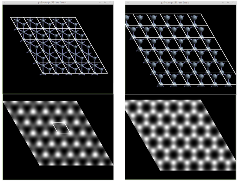
*The sample output for the graphite (left) and graphene (right) STM images should look like the following: | *The sample output for the graphite (left) and graphene (right) STM images should look like the following: | ||
Revision as of 10:58, 17 May 2017
Overview > Ni 100 surface relaxation > Ni 100 surface DOS > Ni 100 surface bandstructure > Ni 111 surface relaxation > CO on Ni 111 surface > Ni 111 surface high precision > partial DOS of CO on Ni 111 surface > vibrational frequencies of CO on Ni 111 surface > STM of graphite > STM of graphene > collective jumps of a Pt adatom on fcc-Pt (001): Nudged Elastic Band Calculation > List of tutorials
Task
Generation of an STM image of a graphene surface.
Input
POSCAR
C: Graphite Lattice
1.0
 +2.4410462393  +0.0000000000  +0.0000000000
 -1.2205231197  +2.1140080551  +0.0000000000
 +0.0000000000  +0.0000000000 +10.0000000000
  2
Cartesian
 +0.0000000000  +0.0000000000  +0.0000000000
 +0.0000000000  +1.4093387034  +0.0000000000
INCAR
general:
  SYSTEM = Graphite surface slap
  ENMAX  = 400
  ISMEAR =    2  ; SIGMA = 0.2
  ALGO= Fast
partial charge densities:
  LPARD = .TRUE.
  LSEPK = .FALSE.
  LSEPB = .FALSE.
  NBMOD = -3
  EINT = -0.1 0.1
#DOS:
  #ISTART = 0
  #ICHARG = 2
  #LORBIT = 11
KPOINTS
K-Points
0
Monkhorst-Pack
9 9 1
0 0 0
Calculation
- This example is carried out in complete analogy to STM of graphite.
- The sample output for the graphite (left) and graphene (right) STM images should look like the following:
Download
To the list of examples or to the main page

